IST Li-ion Battery Simulator | Pack Design & Simulation Software
PR Newswire: IST Li-ion Battery Simulator: design and simulate battery packs for EVs, ESS and more. Cell models, thermal, BMS, safety and AIS-156 checks in one web tool.
Integrated Design and Simulation of Lithium-Ion Battery Packs Across Applications: The IST Li-ion Battery Simulator
Abstract
Designing a lithium-ion battery pack means solving a coupled problem. Electrochemistry sets the voltage and resistance, resistance sets the heat, heat sets the temperature, temperature sets ageing and safety, and the battery management system (BMS) has to protect all of it within milliseconds. In practice these questions are answered in separate tools, by separate teams, at different times. Late-stage surprises such as thermal hot spots, protection timing failures and warranty claims are the usual result.
This article describes the IST Li-ion Battery Simulator (V-10.0.1), a browser-based engineering environment that carries one pack configuration through requirements capture, cell and pack electrochemical design, thermal analysis, BMS design, circuit and electromagnetic design, safety and compliance screening, and report generation. We review the models behind each module, show how the same workflow serves different applications (2W/3W/4W EVs, hybrids, stationary storage, heavy vehicles, marine and aerospace), and state plainly where the tool is a screening instrument and where measured data and accredited testing remain mandatory.
1. Introduction
Lithium-ion batteries now sit at the centre of electric mobility and grid storage. Pack designers face competing requirements:
- Energy and power: range, runtime, peak power and fast-charge targets
- Thermal behaviour: cell-to-cell temperature spread, cooling power, cold-weather charging
- Safety: abuse tolerance, thermal propagation, protection response times
- Life and cost: cycle life, calendar life, warranty exposure, bill of materials
- Regulation: for India, AIS-156, AIS-038 and IS 16893 are relevant, alongside UN R100/R136, UN 38.3, IEC 62619, UL 2580, ISO 26262, IEC 61508 and GB 38031
Commercial multiphysics suites cover these domains well but are costly and fragmented. Open research codes are flexible but rarely connected to a component database, a compliance checklist and a report. The IST Li-ion Battery Simulator aims at the gap between them: an integrated, first-pass design environment that narrows the design space quickly, before expensive 3D CFD, laboratory testing or certification begins.
2. Software architecture and workflow
The simulator runs in a web browser. Calculations are executed server-side, and the interface is organised as a ribbon whose tabs follow the engineering sequence:
Home → Database → Pack Configuration → Thermal Analysis → BMS Design → Circuit Design → Housing → Safety & Compliance → Reports → View
A project is the single container for cells, models, studies and results. Pack topology, once entered (series cells Ns, parallel cells Np, number of modules), is reused by every downstream module, so a design is described once rather than re-keyed in each analysis.
Stage 0: Define Application. The designer records the application type (BEV, HEV/PHEV, 2-wheeler, 3-wheeler, stationary ESS, marine, aerospace, other), duty cycle, target voltage window, energy, continuous and peak power, charge and discharge C-rates, charging standards (CCS1/2, CHAdeMO, GB/T, NACS, AC Type 1/2), environmental envelope, IP rating target, cooling and heating requirements, cell-to-cell thermal barrier, cycle and calendar life targets, depth of discharge, functional safety level (QM to ASIL D), mechanical envelope, and BMS fidelity. This produces a requirement specification and KPI sheet that configures the later stages.
Component databases. Six libraries back the workflow: Cell, BMS, BTMS (thermal management), Master PCB, Busbar and ColdPlate, plus an Other Parts library for contactors, fuses, connectors and harnesses. The status bar of the loaded instance reports 109 cells. The cell list spans LFP, NMC, NCA and LTO chemistries in 18650, 21700, 26650, 32700 and large prismatic formats, from a range of manufacturers. The BMS library includes analog front-end references, 2W/3W/4W, truck/bus, home-storage and rack-level ESS controllers, and a container-scale BESS entry. New datasheets can be authored in-tool and saved as .dat records, so users can add their own verified components.
3. Modelling methods
3.1 Cell and pack electrochemical design
Selecting a cell and a BMS produces a cell model (open-circuit voltage, DC resistance, current limits, energy density) and pack sizing. For the first-order sizing step:
- Series count: Ns = ⌈V_pack,nom / V_cell,nom⌉
- Pack energy: E_pack = Ns · Np · Q_cell · V_cell,nom
- Pack resistance: R_pack ≈ (Ns/Np) · R_cell + R_interconnect
For example, a 16S pack of 100 Ah LFP cells at 3.2 V nominal gives 51.2 V and 5.12 kWh. The tool also checks cell-BMS compatibility (chemistry, over/under-voltage window, series range, current, over-temperature, sensor count) and generates a standards checklist (ARAI AIS-156 / AIS-038 / IS 16893 / UN R100-R136). It writes a thermal battery model (TBM) file intended for downstream CFD linkage.
3.2 Advanced cell modelling (BDS workflow)
Four stages are provided:
- HPPC-based equivalent-circuit (ECM) extraction. Pulse data (t, V, I) are fitted with 1 to 3 RC pairs: V = OCV(SOC) − I·R₀ − ΣV_k, with dV_k/dt = −V_k/(R_kC_k) + I/C_k.
- EIS-based fitting. Impedance spectra (frequency, Z_real, Z_imag) are fitted by complex nonlinear least squares, with an optional solid-diffusion estimate from particle radius.
- Newman pseudo-2D (P2D) solver. A finite-volume reduced-order implementation of the porous-electrode theory of Doyle, Fuller and Newman, with user-set solid diffusivities, reaction rate constants and Bruggeman exponent. Grid density is selectable (coarse, standard, fine).
- Joint parameter identification. Parameters θ = [D_s,neg, D_s,pos, k_neg, k_pos, Bruggeman] are fitted against a measured cycler voltage trace.
Where the user has no test data yet, HPPC, EIS and voltage traces can be auto-generated from the selected cell. Defaults for the P2D solver are a generic graphite/NMC 18650-class parameter set and are described as illustrative.
3.3 Thermal analysis
Four complementary tools, in increasing fidelity and cost:
- Lumped conjugate heat transfer (CHT). N cell nodes and coolant nodes, each a single temperature, connected by conduction and convection resistances: C_i·dT_i/dt = Q_i + Σ(T_j − T_i)/R_ij. Heat generation follows the Bernardi form (irreversible I²R plus entropic term). This allows dozens of coolant-flow or cell-spacing options to be swept in seconds.
- Coolant flow and pressure drop. Hydraulic calculations with density, viscosity, hydraulic diameter, minor losses and mass flow.
- Reduced-order 3D cooling simulation. A voxel model of one module built from the real cell geometry, with anisotropic cells, gaps or barriers, thermal interface and aluminium cold plate. The coolant energy is marched along each channel (liquid) or cell gap (air). Heat-transfer coefficients come from Shah-London, Gnielinski, parallel-plate or Zukauskas correlations. Outputs are T_max, cell-to-cell ΔT, coolant outlet temperature, pressure drop, and pump or fan power, for liquid cold-plate, forced-air and natural-convection options.
- Live thermal imaging. Eight lumped modules in a 2×4 grid, with a staged hysteresis cooling controller (OFF → LOW → MEDIUM → HIGH, independent on/off thresholds per stage), drawn as a false-colour thermal-camera view that runs in the browser. It is useful for tuning controller thresholds.
Thermal runaway. A four-reaction Arrhenius abuse model of the Hatchard/Kim type (SEI decomposition, negative electrode/electrolyte, positive electrode decomposition, electrolyte decomposition) tracks each cell, with onset flagged at dT/dt > 10 °C/min. Kinetics can be recalibrated against accelerating-rate-calorimetry (ARC) traces using a multi-start Levenberg-Marquardt fit. The tool reports honestly which parameters are well determined, since a single narrow-range ARC trace typically constrains only the lowest-onset reaction. Propagation across up to 12 cells can be studied with selectable barriers (air gap, mica, aerogel, ceramic fibre) and cooling on or off.
3.4 BMS design and system-level simulation
The system module assembles the cell model Ns × Np times and provides:
- Pack circuit simulation with resistance mismatch spread across cells
- BMS protection and balancing logic (over/under-voltage, balance threshold on ΔSOC)
- SOC/SOH estimation with an extended Kalman filter (EKF) and recursive least squares (RLS) resistance tracking. The EKF starts deliberately offset from the true SOC to demonstrate convergence, following the standard approach in the BMS literature.
- Closed-loop drive-cycle simulation with vehicle dynamics (mass, rolling resistance, drag, frontal area) over standard cycles: MIDC (India M1/N1), MIDC Part-1 (e-2W/e-3W/LSEV), WMTC Class 3, WLTC 3b, NEDC, UDDS/FTP-72, HWFET and US06
- BMS code generation with SIL/HIL. It emits portable C99 application code (state machine, protections, current limits, passive balancing, EKF, CAN 2.0 frames with a
.dbc, a 10 ms task with HAL hooks), together with SIL test vectors and a python-can HIL replay script. The code is template-based and MISRA-C:2012-oriented, and it is not certified.
3.5 Circuit, electromagnetic and DFM design
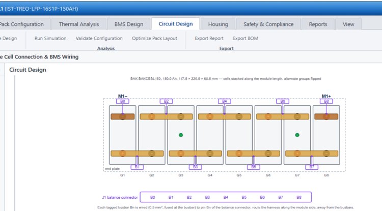
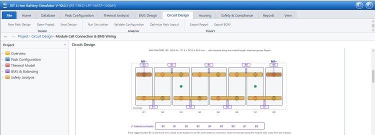
- Cell connection and BMS wiring: busbar layout for prismatic (top view) and cylindrical (top and bottom views) modules, balance-tap and NTC positions, and J1/J2 pin tables for the selected BMS
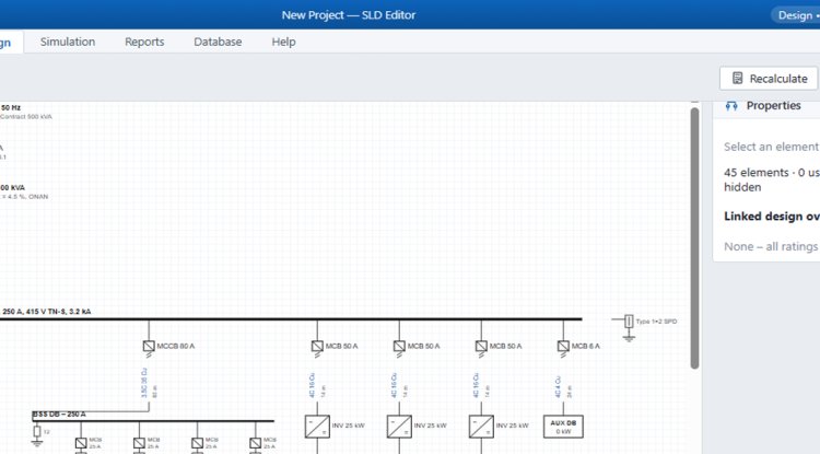
- HV/LV circuit generator: the power chain (modules → service disconnect → contactor with precharge → fuse → current sensor → DC bus), the HVIL loop and the LV BMS network, rendered as a 2D schematic and a rotatable 3D layout
- Magnetostatic and eddy-current analysis: busbar field, force and skin/proximity AC loss, a contactor reluctance-network model with pull-in dynamics, and Hall, Rogowski and shunt sensor transfer functions
- DFM checks: module dimensions from real cell geometry, a worst-case tolerance stack-up, and fuse and precharge-resistor sizing rounded to catalogue ratings with temperature derating
3.6 Ageing, life and warranty prediction
The ageing model is a reduced-order physics model that includes SEI growth (faster at high SOC and temperature), crack-related SEI and stress-driven loss of active material, partially reversible lithium plating at cold or fast-charge conditions, and capacity = min(lithium inventory, anode capacity). The last term allows a knee to appear when anode excess is exhausted. Cycle-fade is calibrated to reproduce the selected cell’s datasheet cycle rating at its stated conditions. A fleet Monte-Carlo then draws daily use, Indian city climate (Delhi, Mumbai, Chennai, Bengaluru, Kolkata, Hyderabad, Ahmedabad, Pune, Jaipur, Lucknow, Guwahati, Leh) and fast-charge share for each simulated unit. It reports expected claim rate, end-of-warranty SOH distribution, and the longest warranty that keeps claims under a target.
4. Application coverage
Because every module reads the same pack definition, the same workflow adapts to very different products:
| Application | Typical design drivers | Where the tool helps most |
|---|---|---|
| 2-wheeler EV (48-60 V, 13S-17S cylindrical or LFP) | Cost, weight, urban cycle, fast-swap or home charging, hot-climate ageing | MIDC Part-1 / WMTC drive-cycle simulation, 2W BMS library entries, warranty Monte-Carlo by city |
| 3-wheeler EV (48-60 V prismatic or cylindrical) | Duty intensity, passenger or cargo load, long daily distance | Drive-cycle energy and C-rate checks, cell derating, life under high daily kilometres |
| 4-wheeler BEV (≈400 V, 96S-108S) | Range, fast charging, ASIL targets, structural packaging | Thermal 3D cooling, BMS closed-loop checks, HV/LV circuit and HVIL design, WLTC/NEDC/UDDS cycles |
| HEV/PHEV | High power-to-energy ratio, shallow cycling, tight thermal windows | Power-cell selection, peak-power pulse analysis (HPPC), cooling sizing |
| Heavy truck and bus | High voltage, long duty, many series cells | Large series counts, stackable BMS, HV safety chain |
| Stationary ESS / home UPS | Cycle life, round-trip efficiency, calendar ageing, rack BMS | ESS duty cycle (solar charge, evening load), ageing at low C-rate, rack and container BMS entries |
| Large BESS (e.g. 768 V container-scale) | Safety propagation, thermal runaway barriers, lifetime economics | Propagation screening with barriers, ageing and warranty, compliance checklists |
| Marine / aerospace / other | Mass, envelope, functional safety, vibration | Target-driven sizing, mechanical envelope and vibration test setup, ASIL/IEC 61508 targets |
The same pack-definition workflow can be re-run across chemistries (for example LFP versus NMC at the same energy). That lets a designer compare thermal load, life and cost before committing to a cell.
5. Safety and compliance screening
A dedicated module organises verification into tracks:
- Track A, electrical performance: capacity and energy verification, and internal resistance verification against design ceilings, with tolerance bands
- Tracks B/C, mandatory safety gates: HV isolation resistance, overcharge, external short circuit, mechanical drop (AIS-156 Annex 8C), mechanical shock (Annex 8D: 18 half-sine shocks, pulse by pack mass) and vibration (Annex 8A: 7-200 Hz sweeps), protection response time against the BMS fault registry (OV, UV, OC, OT, insulation)
- Final Quality Pass Index: safety gates are strict pass/fail, and a single failure or un-run gate blocks release regardless of the performance score. Weighted performance indices are computed only once every safety gate passes.
6. Reporting
A single run executes the electrochemical model, HPPC extraction, conjugate heat transfer, closed-loop drive-cycle simulation, busbar EM analysis, HV/LV topology and thermal-imaging cooling simulation, and assembles an A4 industrial design report. The report contains project details, application context, pack configuration, executive summary, cell and BMS checks, simulation charts, a standards checklist, a complete bill of materials and an approval block, as downloadable HTML or print-to-PDF.
7. Validity, limitations and good practice
Responsible use of any design simulator depends on knowing what it does not do. For this tool, the following should be kept in mind:
- Thermal models are reduced-order. The lumped and voxel models are screening tools. They cannot resolve flow maldistribution, local hot spots or turbulence, so final designs need meshed 3D CFD or test.
- Kinetic and ageing parameters are illustrative until calibrated. Runaway kinetics use reference parameter sets unless fitted to ARC and DSC data, and ageing is calibrated to datasheet ratings, so uncertainty in those ratings carries into warranty predictions.
- Component records need provenance. Cell and BMS entries should be backed by datasheets, with the status field (Active, Draft, In Review, Failed QA) used to control what enters production designs.
8. Who benefits
- Battery pack and EV OEMs shorten the concept stage and test chemistry, topology and cooling options before prototyping
- BMS and electronics teams verify protection logic, fault-injection coverage and SOC/SOH estimator behaviour in closed loop, then generate code for SIL/HIL
- Thermal and safety engineers compare barrier and cooling strategies for propagation, and prepare the evidence trail for certification
- Reliability and warranty teams quantify claim risk by climate and usage before setting warranty terms
- Energy storage developers and EPC teams size packs, racks and containers around duty cycles, ageing and safety
- Researchers and educators use a transparent, equation-level environment to teach ECM, P2D, thermal and ageing concepts
Getting started
This software access available with Lithium-ion Battery Pack Assembly course offered by Academy of EV Technology (AEVT)
Conclusion
Battery design fails at the interfaces: between electrochemistry and thermal behaviour, between thermal behaviour and protection, and between protection and regulation. The IST Li-ion Battery Simulator tackles that problem by placing one shared pack definition behind every analysis, from requirement capture to the final design report, across two-wheelers to grid storage. It is best used as a rapid, transparent screening and concept-design environment. Candidate designs that emerge should then be confirmed with measured cell data, detailed CFD and accredited testing.
Suggested references to cite (please verify details before publication)
- Doyle, M., Fuller, T. F., & Newman, J. (1993). Modeling of galvanostatic charge and discharge of the lithium/polymer/insertion cell. J. Electrochem. Soc., 140, 1526.
- Bernardi, D., Pawlikowski, E., & Newman, J. (1985). A general energy balance for battery systems. J. Electrochem. Soc., 132, 5.
- Hatchard, T. D., MacNeil, D. D., Basu, A., & Dahn, J. R. (2001). Thermal model of cylindrical and prismatic lithium-ion cells. J. Electrochem. Soc., 148, A755.
- Kim, G.-H., Pesaran, A., & Spotnitz, R. (2007). A three-dimensional thermal abuse model for lithium-ion cells. J. Power Sources, 170, 476.
- Plett, G. L. (2004). Extended Kalman filtering for battery management systems of LiPB-based HEV battery packs. J. Power Sources, 134, 252.
- AIS-156 (ARAI), IS 16893, IEC 62619, UN 38.3, UN R100/R136, ISO 26262: current published editions.

: