IST Li-ion Battery Simulator V-10.0.1: Design, Simulate and Publish Battery Packs in One Place
PR Newswire: IST Li-ion Battery Simulator V-10.0.1 teaches battery engineering by doing: you design a real pack, run it on a real drive cycle, and see why it heats, ages, loses range or fails a test. IST offers learning course on battery pack design and simulation with IST Li-ion Battery Simulator V-10.0.1.
Li-ion Battery Pack Design & Simulation with IST Li-ion Battery Simulator V-10.0.1
A simulation practical course that takes engineers from a single lithium-ion cell to a complete, simulated, compliance-screened EV battery pack and a publishable paper.
IST Li-ion Battery Simulator V-10.0.1 lets engineers, manufacturers and researchers take a lithium-ion pack from datasheet to tested design in one simulation software, without building a prototype first.
Why simulate a battery pack before you build it?
Every EV battery pack is a set of trade-offs. More cells in parallel give more range but add weight and cost. Tighter packing saves space but makes cooling harder. A cheaper BMS may limit peak power. And in India, a pack must also pass AIS-156 and BIS tests before it can go on the road.
Finding these trade-offs on a physical prototype is slow and expensive. One failed thermal test can cost weeks. Simulation lets you see the outcome first: how hot the cells get on a real drive cycle, how far the vehicle goes, and whether the design is likely to pass its safety tests.
That is the job of IST Li-ion Battery Simulator, developed by IST Skill. Version 10.0.1 brings cell modelling, pack design, drive-cycle simulation, thermal and cooling analysis, safety screening, housing design and research analysis together in one project file.
From a single cell to a complete pack
The simulator follows the same path an engineer takes in real life:
- Choose a cell. Pick from the built-in database of commercial cells (for example, Samsung INR21700-50E NMC or BYD Blade LFP), or add your own from a datasheet.
- Generate the cell model. The software builds the open-circuit-voltage (OCV) curve, capacity and thermal properties. The BDS module identifies a 2-RC equivalent-circuit model (R0, R1, R2 and time constants) from pulse-test data.
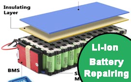
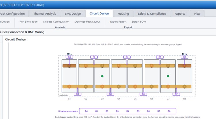
- Configure the pack. Set series and parallel counts (for example 14S15P), select a BMS, and see voltage, energy, resistance and mass instantly. Design checks flag problems such as a BMS current limit that is too low for the motor's peak power.
- Define the application. Enter the vehicle, cooling concept, enclosure and target standards (UN 38.3, IEC 62619, AIS-156, IS 17855).
- Simulate and verify. Run drive cycles, thermal and cooling studies, safety tests and research analyses.
- Report and save. Export a design report with a bill of quantities, figures and tables, and save everything in a single .pro project file.
Key features
|
Module |
What it does |
|---|---|
|
Drive-cycle simulation |
Simulates every cell of the pack on IDC, MIDC, WMTC and other cycles, with vehicle road load, regenerative braking, BMS current limits and cell-to-cell variation. Gives energy use (Wh/km), range and SoC. |
|
Thermal model |
2-RC electro-thermal cell model with temperature-dependent resistance, plus a Bernardi heat model that includes reversible (entropic) heat. |
|
Cooling analysis |
Compares natural convection, die-cast casing, forced air and liquid cold plates. A 3-D solver maps temperature across the whole module, including gap-pad (TIM) thickness and conductivity. |
|
Safety & Compliance |
Screens AIS-156 and IS 17855-type tests (overcharge, short circuit, drop, vibration, isolation and more), and simulates cell-to-cell thermal runaway with different barrier materials. |
|
Housing generator |
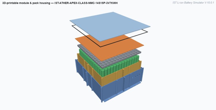
Designs 3-D-printable module and pack housings from the pack layout, with dimensioned drawings, a printed-parts list and STL files. |
|
Design report |
One-click report with design summary, 3-D views, test results and a bill of quantities (BOQ) that includes the housing. |
|
Data flowcharts |
Shows how each project input feeds each figure, table and paper section. |
Research Analysis: from simulation to published paper
The Research Analysis tab turns a project into publication-ready figures and tables. Each chart carries the software watermark and downloads as PNG, and all tables export as CSV. Four sections are available:
- Thermal dependence. Pulse discharge at different temperatures, efficiency, heat and ageing.
- Drive cycle, range and SoC. Energy use, range on several cycles, and SoC estimation on new and aged packs.
- Cell-to-pack thermal & cooling. Heat generation by C-rate, cooling-concept comparison, 3-D module temperatures, manufacturing tolerances and thermal propagation.
- State estimation: SoC, SoH & EIR. Seven SoC estimators compared on the same data: coulomb counting, OCV reset, Luenberger observer, EKF, sigma-point Kalman filter, sliding-mode observer, and an EKF with a hysteresis state. They are tested for precision, temperature effects, reliability (Monte Carlo), sensor faults and battery ageing. The section also shows how the SoC–OCV curve changes over the battery's life, and estimates internal resistance and state of health.
Long studies run in short server slices, so even heavy analyses finish without browser time-outs.
The skills you build, module by module
|
Skill area |
What you learn |
Where in the software |
|---|---|---|
|
Cell fundamentals |
OCV–SoC curves, capacity, NMC vs LFP behaviour, cell selection from a datasheet |
Database, Generate Cell Model |
|
Cell modelling |
Equivalent-circuit models (R0, R1/τ1, R2/τ2), parameter identification from pulse (HPPC) data, temperature dependence of resistance |
BDS module, Research 1 |
|
Pack design |
Series/parallel sizing, voltage window, energy, mass, BMS current limits, design-check reasoning |
Pack Configuration |
|
Vehicle energy |
Road load (rolling, aero, gradient), drivetrain efficiency, regenerative braking, Wh/km and range on IDC, MIDC and WMTC |
Research 2, drive cycles |
|
Heat generation |
Joule heat vs reversible (entropic) heat, the Bernardi equation, heat vs C-rate |
Research 3 |
|
Thermal management |
Choosing natural, casing, forced-air or liquid cooling; 3-D temperature maps; gap-pad (TIM) tolerances |
Research 3, 3-D cooling |
|
Safety engineering |
Thermal-runaway propagation, barrier selection, AIS-156 and IS 17855 test logic |
Safety & Compliance |
|
BMS algorithms |
Coulomb counting, OCV reset, Luenberger observer, EKF, SPKF, sliding-mode observer, hysteresis modelling, SoH and resistance estimation |
Research 4 |
|
Mechanical design |
Module and pack housing, 3-D printing, dimensioned drawings |
Housing tab |
|
Documentation |
Design reports, bill of quantities, publication-ready figures and data flowcharts |
Report, Research Analysis |
Six hands-on exercises to try
Each exercise takes one project and changes one thing. Run it, compare and ask why.
- Same pack, different chemistry. Build a 14S pack with an NMC cell, then repeat with an LFP cell. Compare the OCV curves, the voltage window and the energy. You learn: why LFP needs more cells in series for the same voltage, and why its flat curve matters later for SoC.
- Cold, warm, hot. Run the nine-pulse discharge at 0, 25 and 45 °C. You learn: how resistance rises in the cold, why efficiency falls, and why the pack can hit cut-off early in winter.
- Gentle vs aggressive riding. Run the same scooter on IDC and then WMTC. You learn: why the declared range (IDC) is much higher than highway range, and how heat grows with the square of current.
- Find the cooling you need. Sweep the cooling concepts at 45 °C ambient on WMTC. You learn: how to size the pack-to-ambient conductance (W/K) needed to stay under 55 °C, instead of guessing.
- Stop the chain reaction. In the propagation study, try direct contact, 1 mm mica, 2 mm aerogel and an air gap. You learn: which barriers buy the five minutes of warning that AIS-156 requires.
- Break the sensors. In Research 4, add a current-sensor offset or a stuck voltage sensor. You learn: why coulomb counting drifts, why model-based estimators recover, and why fault detection is part of a BMS.
Learning outcomes
By the end of the course you will be able to:
- select a cell and size a pack for a given vehicle and range target;
- build and identify an equivalent-circuit cell model;
- predict range, energy use and heat on standard Indian and global drive cycles;
- choose and size a cooling concept with numbers, not guesswork;
- screen a design against AIS-156 and IS 17855-type tests and select propagation barriers;
- compare and tune SoC, SoH and resistance estimators, including for LFP;
- produce a professional design report, a BOQ and publication-ready research paper figures.
Why it helps your career
- Job-ready skills. Pack sizing, thermal design, BMS algorithms and compliance are exactly what EV OEMs, pack makers and BMS companies hire for.
- A portfolio you can show. Every project saves as a .pro file with its results, report and figures. Bring it to an interview and walk through your design decisions.
- Research output. Figures and tables export ready for papers, theses and conference posters, and a data flowchart shows how each result was produced.
- Confidence with standards. Working through AIS-156 and IS 17855-type screening makes real lab testing far less mysterious.
Who it is for
- Pack manufacturers and EV start-ups, who need to check cooling, safety and compliance before tooling.
- BMS engineers, who want to compare SoC and SoH algorithms on realistic data.
- Researchers and students, who need reproducible results and publication-ready figures.

ESS News: Energy storage system development, latest news, press release, analysis and opinion from the global energy storage industry.